|
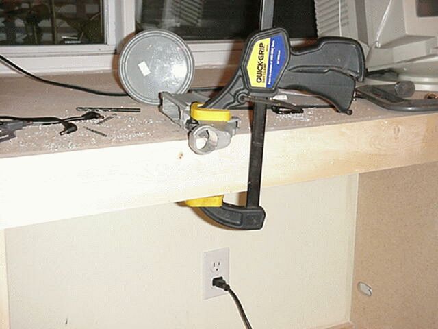
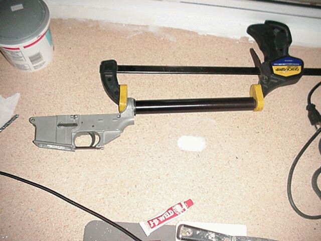
Step 3. Mark the rear take down pin hole. There are several ways to mark this. You could use a ruler, calipers or some other measuring device to mark the spot. www.ar15.com has a good set of blueprints. You could make a pencil rubbing with a piece of paper on a finished receiver. You could guess and hope for the best. I put a spare 1/4" drill bit through the front pivot pin holes in BOTH my DPMS and the 80%. This lines up one end the receiver. To line up the rear end I laid both receivers upside down on a flat level surface (Let's see. maybe my wife's table again) so that the flat spot on top of the buffer tubes lined up the rear ends perfectly then clamped them together! This is really an eyeball/ guess procedure but I got a really good alignment this way.
|
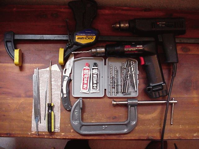
| Jig |
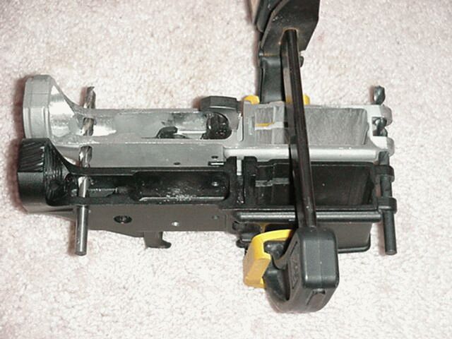
Step 4. Drill the receiver. Once you have the alignment correct it is simple to drill the
holes the trigger pin, hammer pin, and rear take down pin. If you are using a finished
receiver as a jig be careful not to put any pressure on the pin holes of the finished
receiver. Work slowly. William suggested that you drill out each side separately by
moving the finished receiver to each side. I felt that my alignment was very good so I
drilled through both sides at one time. This worked well.
Step 5. Mill the top of the lower receiver. The receiver comes with A LOT of extra material where the top and lower receivers meet. This stops you from being able to close the receiver. It would be great to use a mill or belt sander to remove this but in keeping with the spirit of this project I used a file and sandpaper. I don't know how much I
removed; I don't have a micrometer. I simply put the front pin in and worked the top of the lower receiver with a file until the rear take down hole lined up with the hole in the rear tang of the upper. You may have to "mill" out the lower receiver where the rear tang of the upper fits. (See Step 6) The most challenging part of this process was the radius cut where the lower turns up. I had to use a rat-tail file. This is a file and fit process. This took about 4 hours of filing and sanding but if you use a belt sander it should only take about 1 hour and should give a very even finish.
Step 6. Fit the rear tang into the lower. The area in the lower receiver where the rear take down pin hole goes is too narrow for the upper receiver rear tang (where the pin goes). Simply file this out until the tang will fit. Be careful to take material evenly off both insides so that the upper receiver will be centered to the lower. If you us a Dremmel
this would take about 30 minutes but by hand it was about 1.5 hours.
Step 7. Drill the bolt hold open spring hole. This was a very simply step. I tested drill bits on the finished receiver to find the right size, then marked the correct depth on the bit with a piece of masking tape. This tape was my depth mark. When the tape was at the same depth on the 80% as I had marked on the finished receiver I stopped. I marked the location for this hole by using my calibrated eye (the left one). This is easy because the hole is in such a small limited area.
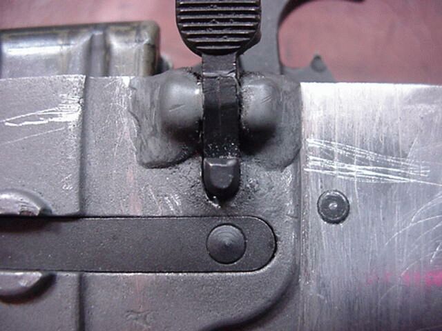
Step 7. Install the bolt hold open lever. The correct way to drill this hole is to get a 3/32x 6" bit from William at TANNERY_SHOP@HOTMAIL.COM
I think they are less than $5. This is how I did it. In keeping with the spirit of this project and since I didn't have this tool, I had to figure how to make this work. It took me several hour of thinking (When I play - I plays hard, when I work - I works hard, when I think - I falls to sleep!) to come up with a solution. I considered leaving it off. I would still have a completely serviceable weapon- the AK doesn't have a bolt hold open and no one would argue with the success of that weapon. But I wanted to have a fully functioning AR-15 so I had to come up with something and there is NO WAY to drill that hole without the right tool. What I will say next will get a lot of insulting flames from the techno-elite on this site but remember this is an insurgent weapon. I took a hacksaw blade and cut into the bolt hold open mounts on the same axis as the hole should be. I cut down to the depth where the bolt hold open pin would lay at the correct depth. This left two "cradles" for the pin to lay in. I then put the pin into the hold open lever, mounted the spring and clamped these into place with my 8" "C" clamp. A little JB Weld replaced the metal that had been removed with hacksaw blade. The next morning I filed/sanded down the JB Weld and had a functional hold open device! I know that this is jury rigging at its highest level but it works very well.
Step 8. Install the magazine release. This was a pretty straightforward installation. There was a small amount of finish filing but the release fit as normal.
Step 9. Install the pistol grip. This was the most fun part of the project. I did not have the correct tap to cut the threads. I thought about JB Welding the handle on or JB Welding the bolt into place. Then I remembered a trick I saw my Dad do. I found a hex head bolt with the same thread as the size and pitch as the grip bolt. I placed this in my "C" clamp vise then cut a hacksaw cut across the threads, along the
length of the bolt on 4 sides. I then tapered the end of the bolt with a file then cleaned up what was left of the threads on the end of the bolt. I had created a tip! My Daddy would have tempered this with a torch to harden it, but since I was working with aluminum, this was more than hard enough. I drilled a hole one bit size smaller than the
bolt. I slowly worked the "tap" into this hole turning only 1/4 of a turn then backing out to clear the cuttings. At first it tried to go in crooked but I remembered that I was smarter that at least 75% of the metal on that receiver so I kept it straight and it cut a clean set of threads. There is room on the receiver where the handle fits to make a test
hole. The handle will cover this.
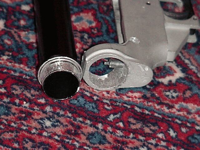
Step 10. Ream out the buffer tube hole. With the upper and lower receiver pinned together, put your finger in the buffer tube hole. This is the path the bolt carrier musttravel during recoil. You have to remove enough material from the inside of the buffer tube hole to allow the carrier to come out of the receivers and into the buffer tube that will be there. Then you have to remove enough material so the tube can be installed.
This hole MUST be centered with the upper receiver or the bolt will rub /bind in the buffer tube. This is another file and fit operation. Since I don't have the tap for this (you can rent it from William for $10) I plan to JB Weld the tube into place. At first I was bothered about this but the buffer tube is only $12 so what the heck. Keep filing and checking that the hole is centered until you can fit the BACK END of the buffer tube into the hole. I did this because the back end is the same size as the front end of the buffer tube without the threads. I removed the threads from the tube because this is easier than enlarging the hole to accept the threads.To test the alignment of the tube, assemble both receivers with the bolt carrier and charging handle. Hold the tube in place and slowly pull the carrier into the tube by using the charging handle. Listen/feel for the carrier rubbing against the inside of the tube. If it gets bound just remove the tube. If it rubs, adjust the hole with a file to align the tube.This took about 3 hours but it could be done in about 30 minutes with a Dremmel.
Step 11. Drill the buffer retaining pin hole. Put the buffer tube in the receiver hole as far as the buffer tube shoulder will allow. This shoulder is behind the treads on the buffer tube. The buffer tube retaining pin has a tit on it. This tit needs to be forward of the tube with the shoulder of the retaining pin under the tube. I used the tit on this pin to mark the hole by dipping the tit into ink and marking a point on the bottom inside of the buffer tube hole as close to the buffer as possible. Use the correct size of bit and measure the depth of the hole on the finished receiver and mark the depth with masking tape. The hole should be tilted toward the front of receiver by 6 degrees. You will have to tilt the bit to clear the buffer tube ring. This is about 6 degrees.
Step 12. Drill the hole for the retaining pins for the safety, rear pin and front pin. This was scary. If you use a drill press it would be easy. But I used my hand drill and was surprised how easy it was to eye ball them. I drew a line on the outside of the reciever as a guide. I'm so good! If I had made a mistake, I would have repaired it with JB Weld tried again.
Step 13. Drill out the alignment hole for the butt stock. Simple operation.
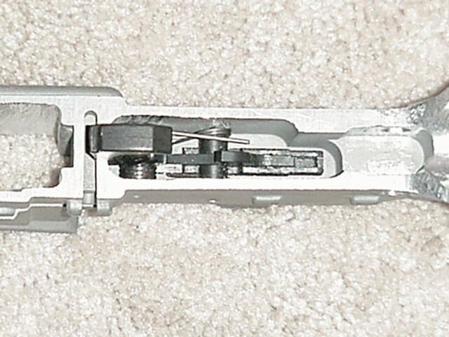
Step 14. Correcting the fire control well. I left this for last because I'm not sure why this happened. With the receiver of or opened and the hammer is froward and resting on the front of the fire control will, it is too far forward. It goes past Top Dead Center. This may be because the hammer pin hole is too far forward or because the divider between the fire control well and the bolt hold open well is slightly narrower than My DPMS. This causes the top of the hammer to hit the bottom of the firing pin if you try to close the receiver with the hammer forward. I put some JB Weld in the well where the hammer rests and the problem was corrected. You should never drop the hammer with the receiver open on and AR-15. I have seen several damaged in the Army this way.
I fired a few rounds behind a friend's barn and it works perfectly. I'll be putting a lot of ammo through it next weekend.
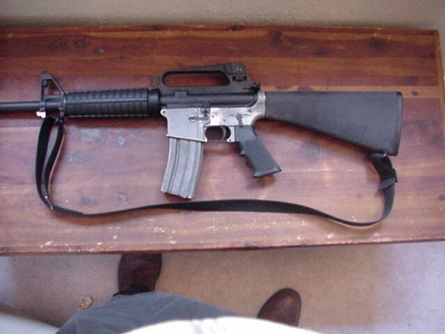
Conclusion. This was a fun project, well worth the $44. I will be firing Betsy next weekend to test durability. I am a retired soldier and I would not be afraid to use the rifle any time in the defense of my home and country.
|
|
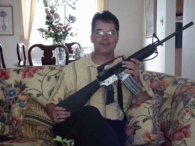
| Blakely Noble and the Mujahadeen AR-15 |
I had a request to post my parkerizing solution mixture so here it is:
I use a mixture of 1/2 gallon technical grade Phosphoric acid to 8 ounces manganese dioxide . The Phosphoric acid is mixed with 9 gallons water in a stainless trough and brought to a rolling boil. The Manganese Dioxide is then slowly mixed in the solution and boiled for 10 minutes. When the parts are ready to parkerize after blasting with coarse ground glass I reheat the solution to 190 degrees F and immerse the part in the solution until foaming stops.
Then I remove the part from the solution, rinse with cold water, oil with a mixture of 1 gallon WD40 and 1 quart chainsaw oil, dry and re-oil. I have built over 300 guns this year alone using this method. The finished guns are near black and retain oil very well.
|